
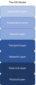
The Open System Interconnection model is a conceuptual model that standardises the communication functions of a network system.
The OSI model divides the communication functions into seven different sections, which ranges from the physical method of connection and transmission at the lowest part of the model (e.g. a CAT5 network cable) to the application that communicates over the network at the highest part of the model (e.g. HTTP with Internet Explorer, Mozilla Firefox, Google Chrome)
For new network engineers, the OSI model is a great place to start in order to get familar with how data gets across a typical network.
Layer 1 – Physical Layer
The physical layer represents the hardware that sends and recieves the stream of bits (0’s and 1’s) through the physical network connection. Many methods of physical connection exist such as electrical via twisted pair cable, laser light via a fibre connection, or radio using a wireless access point. If the Layer 1 physical connection between devices does not exist, the rest of the layers (2-7) will not function.
Layer 2 – Data Link
Layer 2 controls how packets from the upper layers are encoded into bits, and decoded from bits into packets from the physical layer. The data link layer also provides error and flow control to packets transmitting across media. MAC addresses feature at this layer, a permanent unique address associated with the network hardware to identify it among network endpoints.
Layer 3 – Network Layer
The network layer is where IP addressing and packet routing is handled to enable data transmission. Decisons of where and what method a packet is routed is most commonly determined at network layer.
Layer 4 – Transport Layer
TCP and UDP function at the transport layer. The transport layer manages converting network data into packets to be routed across a network. The management and some cases error checking of these packets is performed at this layer.
Layer 5 – Session Layer
The session layer is responsible for the setting up, co-ordination and termination of conversations between two network devices. TCP and UDP provide the services at this layer as well as on the transport layer.
Layer 6 – Presentation Layer
Layer 6 is usually part of the operating system on the hardware, which converts the incoming and outgoing packets into a recognised format within the operating system.
Layer 7 – Application Layer
The application is layer is a platform in which an application on the operating system itself can use to establish whether it can perform communications over the network. It provides services to the application on the operating system allowing the application to decide whether it can communicate over the network at that moment, or even whether there is a network or end point to communicate too.
Layer 8 – Human Layer (Unofficially)
Some network engineers joke about a network issue being at Layer 8, the human that is driving or operating the device 🙂
Leave a Reply