
Goal: To experiment with MSP (Multiple Spanning Tree)
Topology and Setup
In this deployment we’ll test with three L2/L3 switches in the following topology
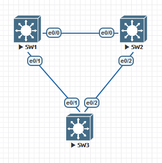
On switches 1,2,3:
Configure the hostname
SW1(config)#hostname SW1
Configure VLANs 2,3,4,5
SW1(config)#vlan 2,3,4,5
Change spanning tree mode to MST
SW1(config)#spanning-tree mode mst
Map VLANs 2,3,4,5 to instance 1
SW1(config)#spanning-tree mst configuration
SW1(config-mst)#instance 1 vlan 2,3,4,5
Assign SW1 as Root bridge:
SW1(config)#spanning-tree mst 0 root primary
SW1(config)#spanning-tree mst 1 root primary
Configure each interconnected port as trunk and include all VLANs
SW1(config)#interface range e0/0 - 1
SW1(config-if-range)#switchport trunk encapsulation dot1q
SW1(config-if-range)#switchport trunk allowed vlan 1,2,3,4,5
SW1(config-if-range)#switchport mode trunk


SW2(config)#interface range ethernet 0/0, e0/2
SW2(config-if-range)#switchport trunk encapsulation dot1q
SW2(config-if-range)#switchport trunk allowed vlan 1,2,3,4,5
SW2(config-if-range)#switchport mode trunk

SW3(config-vlan)#interface range ethernet 0/1 - 2
SW3(config-if-range)#switchport trunk encapsulation dot1q
SW3(config-if-range)#switchport trunk allowed vlan 1,2,3,4,5
SW3(config-if-range)#switchport mode trunk
Review the situation of MST on SW1:
SW1#show spanning-tree mst
 MST0    vlans mapped:   1,6-4094
 Bridge        address aabb.cc00.1000  priority      24576 (24576 sysid 0)
 Root          this switch for the CIST
 Operational   hello time 2 , forward delay 15, max age 20, txholdcount 6
 Configured    hello time 2 , forward delay 15, max age 20, max hops    20
 Interface        Role Sts Cost      Prio.Nbr Type

 Et0/0            Desg FWD 2000000   128.1    Shr
 Et0/1            Desg FWD 2000000   128.2    Shr
 Et0/2            Desg FWD 2000000   128.3    Shr
 Et0/3            Desg FWD 2000000   128.4    Shr
 MST1    vlans mapped:   2-5
 Bridge        address aabb.cc00.1000  priority      24577 (24576 sysid 1)
 Root          this switch for MST1
 Interface        Role Sts Cost      Prio.Nbr Type

 Et0/0            Desg FWD 2000000   128.1    Shr
 Et0/1            Desg FWD 2000000   128.2    Shr
The Importance of MST Regions and Trunked VLANs
This was described in Multiple Spanning Tree Instances (MSTIs)MST Misconfiguration Scenarios
All ports for MST0 and MST1 are designated, with SW1 being root we would expect the e0/2 link between SW2 and SW3 to be blocked on one port; SW3 is blocked on e0/2 due to having a higher MAC address than SW2.
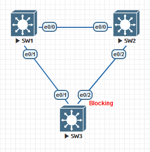
VLANs 1,2,3,4,5 will travel from SW2, to SW1, to SW3.
If we remove VLAN3 from SW1 to SW2; will it disrupt communications due to the blocked port to SW3?
We’ll remove VLAN3 from the trunk on SW2:
SW2#show run int e0/0
 Building configuration…
 Current configuration : 125 bytes
 !
 interface Ethernet0/0
  switchport trunk allowed vlan 1-5
  switchport trunk encapsulation dot1q
  switchport mode trunk
 end
SW2(config)#interface e0/0
 SW2(config-if)#switchport trunk allowed vlan remove 3
SW2#show run int e0/0
 Building configuration…
 Current configuration : 129 bytes
 !
 interface Ethernet0/0
  switchport trunk allowed vlan 1,2,4,5
  switchport trunk encapsulation dot1q
  switchport mode trunk
 end
SW2 no longer has a VLAN3 link to SW1 to reach SW3. But it does have a direct link to SW3 – Is that now unblocked? Let’s check on SW3
SW3#show spanning-tree vlan 3
 MST1
   Spanning tree enabled protocol mstp
   Root ID    Priority    24577
              Address     aabb.cc00.1000
              Cost        2000000
              Port        2 (Ethernet0/1)
              Hello Time   2 sec  Max Age 20 sec  Forward Delay 15 sec
 Bridge ID  Priority    32769  (priority 32768 sys-id-ext 1)
              Address     aabb.cc00.3000
              Hello Time   2 sec  Max Age 20 sec  Forward Delay 15 sec
 Interface           Role Sts Cost      Prio.Nbr Type

 Et0/1               Root FWD 2000000   128.2    Shr
 Et0/2               Altn BLK 2000000   128.3    Shr
The port is still being blocked, VLAN3 communication is broken!
It is important that if a group of VLANs are included in a MST region, that that their trunking set-up is also similar.
We’ll move VLAN3 to it’s own MST region on all three switches:
SW3(config)#spanning-tree mst configuration
SW3(config-mst)#instance 2 vlan 3
On SW1 we’ll keep it as the root:
SW1(config)#spanning-tree mst 2 root primary
Does VLAN3 now have a route to SW3 from SW2?
SW3#show spanning-tree mst 2
 MST2    vlans mapped:   3
 Bridge        address aabb.cc00.3000  priority      32770 (32768 sysid 2)
 Root          address aabb.cc00.1000  priority      24578 (24576 sysid 2)
               port    Et0/1           cost          2000000   rem hops 19
 Interface        Role Sts Cost      Prio.Nbr Type

 Et0/1            Root FWD 2000000   128.2    Shr
 Et0/2            Desg FWD 2000000   128.3    Shr
Yes! To make sure that SW2 is also not blocking any ports:
SW2#show spanning-tree mst 2
 MST2    vlans mapped:   3
 Bridge        address aabb.cc00.2000  priority      32770 (32768 sysid 2)
 Root          address aabb.cc00.1000  priority      24578 (24576 sysid 2)
               port    Et0/2           cost          4000000   rem hops 18
 Interface        Role Sts Cost      Prio.Nbr Type

 Et0/2            Root FWD 2000000   128.3    Shr
 SW2#
To complete the MST instance layout, here is the output for SW1:
SW1#show spanning-tree mst 2
 MST2    vlans mapped:   3
 Bridge        address aabb.cc00.1000  priority      24578 (24576 sysid 2)
 Root          this switch for MST2
 Interface        Role Sts Cost      Prio.Nbr Type

 Et0/0            Desg FWD 2000000   128.1    Shr
 Et0/1            Desg FWD 2000000   128.2    Shr
Mixing Spanning Tree Modes
This was described in Multiple Spanning Tree Boundaries
We’ll now mix in multiple spanning tree modes to see how MSTP works in a multi STP topology network, the previous labs configuration will be used:
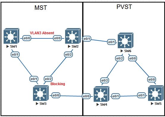
On SW4, SW5, SW6, we’ll create VLANS 2,3,4,5, trunk them together and across to the MST switches.
SW6(config)#hostname SW6
SW6(config)#vlan 2,3,4,5
SW6(config-vlan)#interface range e0/0 - 2
SW6(config-if-range)#switchport trunk encapsulation dot1q
SW6(config-if-range)#switchport trunk allowed vlan 1,2,3,4,5
SW6(config-if-range)#switchport mode trunk
Switch(config)#hostname SW5
SW5(config)#vlan 2,3,4,5
SW5(config-vlan)#interface range e0/0 - 1
SW5(config-if-range)#switchport trunk encapsulation dot1q
SW5(config-if-range)#switchport trunk allowed vlan 1,2,3,4,5
SW5(config-if-range)#switchport mode trunk


Switch(config)#hostname SW4
SW4(config)#vlan 2,3,4,5
SW4(config-vlan)#interface range e0/0 - 2
SW4(config-if-range)#switchport trunk encapsulation dot1q
SW4(config-if-range)#switchport trunk allowed vlan 1,2,3,4,5
SW4(config-if-range)#switchport mode trunk
We’ll add the new trunk configuration to switches SW2 and SW3 too:
SW2(config)#int e0/1
SW2(config-if)#switchport trunk encapsulation dot1q
SW2(config-if)#switchport trunk allowed vlan 1,2,3,4,5
SW2(config-if)#switchport mode trunk

SW3(config)#int e0/0
SW3(config-if)#switchport trunk encapsulation dot1q
SW3(config-if)#switchport trunk allowed vlan 1,2,3,4,5
SW3(config-if)#switchport mode trunk
At this time, the root bridge is a MST running switch, the PVST switch SW4 sees the root for all VLANs across the boundary:
SW4#show spanning-tree interface e0/0
 Vlan                Role Sts Cost      Prio.Nbr Type

 VLAN0001            Root FWD 100       128.1    Shr Peer(STP)
 VLAN0002            Root FWD 100       128.1    Shr Peer(STP)
 VLAN0003            Root FWD 100       128.1    Shr Peer(STP)
 VLAN0004            Root FWD 100       128.1    Shr Peer(STP)
 VLAN0005            Root FWD 100       128.1    Shr Peer(STP)
 SW4#
Let’s change VLAN4 root to a PVST enabled switch and observe want happens.
SW5(config)#spanning-tree vlan 4 root
SW4 detects this change:
SW4#show spanning-tree interface e0/1
 Vlan                Role Sts Cost      Prio.Nbr Type

 VLAN0001            Desg FWD 100       128.2    Shr
 VLAN0002            Desg FWD 100       128.2    Shr
 VLAN0003            Desg FWD 100       128.2    Shr
 VLAN0004            Root FWD 100       128.2    Shr
 VLAN0005            Desg FWD 100       128.2    Shr
SW3 is now blocking the link between itself and SW4:
SW3#show spanning-tree vlan 4
 MST1
   Spanning tree enabled protocol mstp
   Root ID    Priority    24577
              Address     aabb.cc00.1000
              Cost        2000000
              Port        2 (Ethernet0/1)
              Hello Time   2 sec  Max Age 20 sec  Forward Delay 15 sec
 Bridge ID  Priority    32769  (priority 32768 sys-id-ext 1)
              Address     aabb.cc00.3000
              Hello Time   2 sec  Max Age 20 sec  Forward Delay 15 sec
 Interface           Role Sts Cost      Prio.Nbr Type

 Et0/0               Desg BKN*2000000   128.1    Shr Bound(PVST) *PVST_Inc
 Et0/1               Root FWD 2000000   128.2    Shr
 Et0/2               Altn BLK 2000000   128.3    Shr
Along with SW2, this has isolated both of the STP topologies from each other:
SW2#show spanning-tree vlan 4
 MST1
   Spanning tree enabled protocol mstp
   Root ID    Priority    24577
              Address     aabb.cc00.1000
              Cost        2000000
              Port        1 (Ethernet0/0)
              Hello Time   2 sec  Max Age 20 sec  Forward Delay 15 sec
 Bridge ID  Priority    32769  (priority 32768 sys-id-ext 1)
              Address     aabb.cc00.2000
              Hello Time   2 sec  Max Age 20 sec  Forward Delay 15 sec
 Interface           Role Sts Cost      Prio.Nbr Type

 Et0/0               Root FWD 2000000   128.1    Shr
 Et0/1               Desg BKN*2000000   128.2    Shr Bound(PVST) *PVST_Inc
 Et0/2               Desg FWD 2000000   128.3    Shr
The change to this port status is to protect the STP topology from any networking loops. Since VLAN4 is receiving a better BPDU in comparison to the other VLANs in the same MST instance (2 and 5), it will block it.
We will need to move VLAN4 to it’s own MST instance or set the PVST to be the root for VLANs 2 and 5 too. We will set the PVST to be root for VLANs 2 and 5 and observe.
SW5(config)#spanning-tree vlan 2 root primary
SW5(config)#spanning-tree vlan 5 root primary
We’ll now check the boundary interface between SW4 and SW3.
SW3#show spanning-tree interface ethernet 0/0
 Mst Instance        Role Sts Cost      Prio.Nbr Type

 MST0                Desg BKN*2000000   128.1    Shr Bound(PVST) *PVST_Inc
 MST1                Desg BKN*2000000   128.1    Shr Bound(PVST) *PVST_Inc
 MST2                Desg BKN*2000000   128.1    Shr Bound(PVST) *PVST_Inc
Still blocked! Even though VLANs 2,4,5 (The entire region 1) roots are now in the PVST VLAN.
Let’s attempt letting the PVST instance take control of VLAN1, which is region 0 in the MST.
SW5(config)#spanning-tree vlan 1 root primary
A message generated on SW3:
*Mar 22 22:13:52.362: %SPANTREE-2-PVSTSIM_OK: PVST Simulation inconsistency cleared on port Ethernet0/0.
The port has transitioned to a blocking state!
SW3#show spanning-tree interface ethernet 0/0
 Mst Instance        Role Sts Cost      Prio.Nbr Type

 MST0                Altn BLK 2000000   128.1    Shr Bound(PVST)
 MST1                Altn BLK 2000000   128.1    Shr Bound(PVST)
 MST2                Altn BLK 2000000   128.1    Shr Bound(PVST)
Let’s check our other interconnection into the PVST network.
SW2#show spanning-tree interface ethernet 0/1
 Mst Instance        Role Sts Cost      Prio.Nbr Type

 MST0                Mstr BKN*2000000   128.2    Shr Bound(PVST) *PVST_Inc
 MST1                Mstr BKN*2000000   128.2    Shr Bound(PVST) *PVST_Inc
 MST2                Mstr BKN*2000000   128.2    Shr Bound(PVST) *PVST_Inc
 SW2#
Still blocking – could it be VLAN1? Let’s try adjusting that to let the PVST network take control of it:
SW1(config)#spanning-tree mst 0 priority 32768
SW2#show spanning-tree interface ethernet 0/1
 Mst Instance        Role Sts Cost      Prio.Nbr Type

 MST0                Root BKN*2000000   128.2    Shr Bound(PVST) *PVST_Inc
 MST1                Mstr BKN*2000000   128.2    Shr Bound(PVST) *PVST_Inc
 MST2                Mstr BKN*2000000   128.2    Shr Bound(PVST) *PVST_Inc
 SW2#
Does not to be appear the case – though a clue did appear in the message buffer:
*Mar 22 22:20:55.945: %SPANTREE-2-PVSTSIM_FAIL: Blocking root port Et0/1: Inconsitent inferior PVST BPDU received on VLAN 3, claiming root 24576:aabb.cc00.1000
Aimed with this error message, we can look for some guidance on what to do on this situation. Here is a great summary on the community Cisco forum.
Either configure your MST switch so that its priority in MSTI 0 is lower than the priority of any PVST switch in any VLAN in the PVST region.
This will make the MST switch to become the root switch for MSTI0 as well as a root switch for each and every VLAN in the PVST region.
Or configure the PVST switch so that it becomes the root for both the PVST and MST regions:
In VLAN 1, it has a priority lower than the priority of the current MSTI 0 root
In VLANs 2-4094, it has a priority lower than its own priority in VLAN 1
Peter Paluch; Cisco Community Forum
The goal here was to allow the PVST switch to be the root. Aimed with this knowledge we decreased the priority further of VLANs 2 and left VLAN1 as it was:
SW5(config)#spanning-tree vlan 2-5 priority 16384
And we reached success!
SW2#show spanning-tree interface e0/1
 Mst Instance        Role Sts Cost      Prio.Nbr Type

 MST0                Root FWD 2000000   128.2    Shr Bound(PVST)
 MST1                Mstr FWD 2000000   128.2    Shr Bound(PVST)
 MST2                Mstr FWD 2000000   128.2    Shr Bound(PVST)
SW3#show spanning-tree interface e0/0
 Mst Instance        Role Sts Cost      Prio.Nbr Type

 MST0                Altn BLK 2000000   128.1    Shr Bound(PVST)
 MST1                Altn BLK 2000000   128.1    Shr Bound(PVST)
 MST2                Altn BLK 2000000   128.1    Shr Bound(PVST)
 SW3#
It seems easier to have the MST switch as the root; but if you wish to have PVST as the root it is important to make sure your VLAN numbers above 1 are lower priority than VLAN1 itself.
Leave a Reply