
Objectives:
Describe flow logic of the next generation firewall
Create a security zone
Describe the differences between Tap, Virtual Wire, Layer 2 and Layer 3
Create and configure a virtual router
Define a static default route
Configure a VLAN interface
Configure a loopback interface
The flow logic of a next generation firewall
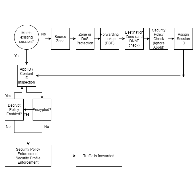
The diagram above shows the flow logic of a packet travelling through a Palo Alto Firewall.
If traffic is decrypted by a policy, it is re-encrypted when traffic is forwarded on from the firewall.
The policy check also checks any IP addresses before network address translation occurs
Flexible Deployment Options
Tap
Tap allows traffic to be mirrored to the firewall, allowing for application, user, and content visibility without any inline deployment.
Tap is suitable for an evaluation and audit of the existing network
The Tap interface can be connected to a core switches switch port analyser, otherwise known as SPAN, to recieve a mirror of packets traveling through the network for the Palo Alto to analyse
Virtual Wire
App-ID, Content-Id and SSL Decryption is can be used with Virtual Wire. It also includes network address translation capabilities.
VWire mode allows the firewall to be inserted into an existing topology without requiring any reallocation of network addresses or redesign on the network topology. All protection and decryption features of the firewall can be used
Layer 3
Layer 3 offers all the options that virtual wire has. In addition Layer 3 offers virtual routers, virtual private networks and routing protocols
The firewall can mix and match these interface types on a single device.
Security Zones and Security Policies
Palo Alto firewalls use the concept of security zones to secure and manage networks.
Different security policy rules are created to control traffic to and from each zone
The physical location of the zone does not matter, a single zone can be at different locations throughout an enterprise.
Descriptive zone names should be chosen that help designate specific types of business, functions, location or access privileges
By default the Palo Alto firewall allows intrazone traffic, and a denys interzone traffic
In-band network interfaces
There are three types of in-band network interfaces to allow traffic flow across and enterprise
They are labeled with the format ethernet n/n
The first type is on a single-slot firewall, where the interfaces are ethernet1/1, ethernet1/2 and so on. The second number represents the inband port.
On a multi-slot firewall, the first number represents the slot number, the second number represents the inband port
Logicial interfaces can be sub-interfaces on a physical interface, in a format of ethernet1/1.1 or ethernet1/1.2
A physical port or subinterface can only be assigned to a single zone. A zone can contain multiple physical or logical interfaces
Interface Zone Types
Tap Zone contains Tap interfaces
Layer 2 Zones contain Layer 2 intefaces
Tunnel zones do not contain any interfaces, they are used for a feature called tunnel content inspection and for a specific scenario that involves tunnel-in-tunnel encapsulation
Virtual Wire zone contains virtual wire interfaces
Layer 3 zones can contain layer 3 interfaces, VLAN interfaces, Loopback interfaces or Tunnel interfaces. All these interface types can be assigned IP addresses
HA intefaces are not used to control network traffic, and used for synchronisation of a pair of firewalls deployed in a high availability configuration. They cannot be placed in a security zone
The management interface also does not control network traffic, and is used for firewall management. It cannot be assigned to a zone
Tap Interfaces
Tap interfaces allow passive monitoring of switch traffic from the SPAN or mirror port.
The firewall cannot control or perform traffic shaping on ports where it is configured as a tap interface
If the port passes mirror traffic, the tap interface can only support SSL Inbound Decryption
Even though the firewall cannot block traffic, it can still identify the traffic
This is useful for the administrator when it comes to configuring sercurity rules on whether to permit or deny traffic
Virtual Wire Interfaces
A virtual wire interface binds two firewall interfaces together. It is typically used when no switching or routing is required by the firewall. It sits transparently between two network devices so no configuration changes are required. No MAC address or IP address is assigned to either virtual wire interface
Creating the virtual wire is completed in two steps:
- Create the virtual wire object
- Configure the virtual wire interfaces
It should be noted though that Palo Alto firewalls come factory preconfigured with Ethernet ports 1 and 2 preconfigured as virtual wire interfaces, allowing all untagged traffic through.
Since network traffic flows through the firewall, the firewall can examine, shape, and block traffic. The virtual wire configuration can take advantage of many Palo Alto features such as App-ID, Content-ID, NAT, QoS, SSL decryption and User-ID
A virtual wire is also known as a ‘bump in the wire’ deployment or ‘transparent in-line deployment’.
As the virtual wire is transparent between other devices, it does not support routing or firewall management traffic as no IP address is assigned to the virtual wire interface. A virtual wire configuration can also not service as a end point for a VPN tunnel
Virtual Wire Subinterfaces
A virtual wire sub-interace can read and process traffic based on several factors:
- VLAN tags ( 1 – 4094)
- IP classifers (untagged, traffic, source IP)
- VLAN tags and IP classifers (source IP)
The IP classifer can be made up of a specific address, a range of addresses, ro a subnet address.
Each sub interface can be assigned to a seperate security zone, allowing granular policy controls to traffic flows arriving or leaving through the same port.
Layer 2 interfaces
A layer 2 interface provides switching between two or more interfaces through a VLAN object. This is normally used when no routing is required
To create a layer 2 interface:
- Create a VLAN object
- Configure the Layer 2 interfaces that the VLAN object connects too
Note that the firewall does not take part in any spanning tree protocol. The firewall does forward STP packets that arrive from external switches in the VLAN object to the other switches.
In Layer 2 mode the fireewall can support App-ID, Content-ID, User-ID, SSL decryption and QoS. A layer 2 interface does not support routing or firewall management as no IP addresses are assigned to a layer 2 interface
Layer 2 sub-interfaces
Like virtual wire, layer 2 can be divided up into sub interfaces. Sub interfaces can be assigned to different zones and security policies can be applied to them.
VLAN traffic is isolated by a sub-interface, this is caused by two factors:
- Need routing between VLANs
- Security policy blocks interzone traffic by default
This is a good configuration candidate for multi tenanted networks
Layer 3 interfaces
The layer 3 interface type allows routing of traffic between multiple layer 3 interfaces.
As a layer 3 interface can carry out routing, network traffic can flow through the firewall between different layer 3 interfaces. The firewall can examine, shape and block traffic as it traverses these interfaces
The routing between layer 3 interfaces is carried out by an internal virtual router inside the Palo Alto firewall
A layer 3 deployment typically takes more work as it usually requires network reconfiguration in the organisation.
A layer 3 firewall supports App-ID, Content-ID, User-ID, SSL decryption, NAT and QoS. Additionally, unlike the other interface types so far, the layer 3 interface can support management traffic and VPN traffic as it is assigned an IP address
A layer 3 interface supports IPv6 too, these can deployed seperately or as part of a dual stack configuration. The firewall needs to be enabled to use IPv6 though.
This can be turned on in Device -> Setup -> Session -> Session Settings -> [Gear Icon], click the option ‘Enable IPv6 Firewalling’
Layer 3 sub-interfaces
Similar to Layer 2 sub interfaces, traffic in each VLAN is isolated; requiring a virtual router to connect together, and security policy blocks interzone traffic flow by default.
To allow trafifc to flow between zones, appropiate security rules need to be configured.
If two seperate sub-interfaces have the same VLAN number, the firewall will use ethernet witching to pass traffic between the zone interfaces.
If two seperate sub-interfaces have different VLAN numbers, the traffic needs to pass through the virtual router on the IP layer.
Virtual Routers
The Palo Alto makes use of an internal virtual router to reach other subnets
The virtual router can be configured in several ways to reach other subnets. Using static routes, or with the use of a dynamic routing protocol.
The Palo Alto can support the BGPv4, OSPFv2, OSPFv3 and RIPv2 routing protocols. The Palo Alto can also route multicast with the PIM-SM (spare mode) v2 and PIM-SSM (source specific multicast) v2 multicast routing protocols.
Whilst on the topic of multicast, host facing interfaces have multicast support with IGMP v1, v2 and v3.
The Palo Alto firewall can be configured with multiple virtual routers, and have inter virtual router links between them.
Multiple Static Default Routes
Multiple static default routes can be configured on the Palo Alto firewall. When assigned different metrics, the route with the lowest metric is chosen for use by the Palo Alto firewall.
Path monitoring can be used to determine whether a default route is valid. If the router is no longer deemed to be valid the Palo Alto firewall will switch to the next higher metric route in it’s routing table
Path monitoring will continue to monitor all paths, even after a failure. If the path monitoring detects a lower metric default router is usable again, it will switch back to that default route with the lower metric.
VLAN Interfaces
Network interfaces that are attached to a layer 2 interface, and a vlan object can be attached to the virtual router through the configuration of a VLAN interface.
A VLAN interface can be assigned an IPv4 or IPv6 address and attached to a virtual router. This provides a path from the Layer 2 interfaces of the firewall to the Layer 3 interfaces of the firewall
Loopback Interfaces
The loopback interface is a logical non physical interface that be reached through a physical interface or sub inteface.
It behaves just like a host interface that can serve clients and is assigned an IP address.
Firewall services provided through the loopback interface could be a access point to the management web interface through HTTPs, a GlobalProtect Portal, a GlobalProtect Gateway, or an IPSec VPN tunnel endpoint.
Policy Based Forwarding
Policy based forwarding allows traffic to take an alternative path compared to the next hop specified in the routing table. They are typically used to specify an outgoing interface for security or performance reasons.
Policy based forwarding does not apply to traffic that originates locally from the firewall itself. Examples would be an IPSec VPN, GlobalProtect, or traffic originating from a virtual router
Policy Based Forwarding can be configured from Policies -> Policy Based Forwarding
These rules can be customised to specify matching criteria such as source zone or interface, source or destination IP address, application, or destination port. If the criteria is matched, the rule can be set to specify an outgoing interface
Policy based forwarding contains a feature that allows path monitoring to verify connectivity to the outgoing interface/next hop address. This allows the firewall to direct traffic through an alternative outgoing interface if the interface specified by the policy based forwarding becomes unavaiable for any reason.
An ICMP ping is used as heartbeats to verify the next hop IP address is indeed reachable.
The path monitoring / montioring profile can be configured to have a threshold number of heartbeats to determine whether the external next hop IP address is unreachable. If the monitoring profile picks up that the IP address is unreachable, the rule can be disabled or an alternative route specified. If the rule is disabled the virtual router will use it’s routing table to determine the next hop IP address to be used.
Once fail over or wait recover action is taken, the profile continues to check if the next hop IP address is reachable. If it becomes reachable the firewall will automatically revert to using the policy based forwarding rule
Leave a Reply